47+ solidworks sheet metal flat pattern not working
This question has a validated answer. When functioning normally this derived configuration SHOULD have the flat pattern feature unsuppressed in the parts feature tree however it is easy to accidentally suppressunflatten it.

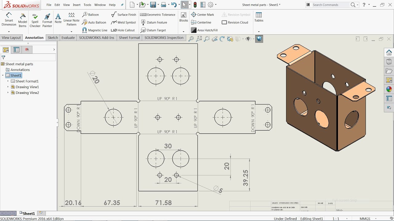
Pin On Solidworks Sheet Metal
Dont try to convert or insert bends with sheetmetal.

. It was a 2D sketch that I projected to a surface and then thickened to 375. This means that some functions may not work as expected. In the FeatureManager design tree do one of the following.
Right-click Flat-Pattern and select Unsuppress. This was originally created as a standard part. Unfold select face and bends Make a cutout at the corners so that the plat does not intersect itself Fold.
Although the Swept Flange tool is a wonderful part of the Sheet Metal toolset I have had many users comment about how frustrated they were that. At the sheet-metal feature check auto relief 2mm obround. Extend your SOLIDWORKS portfolio to the cloud and take your collaboration agility and speed to market to the next level through secure.
Friends we have another youtube channel on the Topic H. Hi I am struggling to flat pattern this part. Normally you should use the closed corner feature but this feature did not seem to appear.
BUT when I create a new drawing and insert a flat pattern view on the sheet the view shows a folded part instead of a flat part. I do as Mandrake22 suggests and in the mirrored part I InsertBends. SolidWorks 2014 introduces some new sheet metal tools to make your design process easier than ever.
In my experience Verdana has been clean not only for Solidworks but for CNC mill laserwaterjet paths also. Middle School Drawing Lesson Plans Printable Drawing Lessons For Kids Directed Drawing Lessons For Kids Contour Line Drawing Lesson Plan. Yes its a mess lol.
Whenever you insert a sheet metal part into a drawing SOLIDWORKS automatically creates a derived configuration in the part file for the flat pattern. Hello all I am designing a sheet metal part. Using a plain text is not an issue for my applications.
Offset a plane and on that new plane draw the other profile. If I insert exactly the same dimensions to a simple 90 degree bend in Fusion and then in our pressbrake the flat pattern dimension has a differens in between 05mm-15mm depending on the thicknes of the material. 403k members in the SolidWorks community.
All features before Flat-Pattern1 in the FeatureManager design tree appear in both the folded and flattened sheet metal part. By HerrTick Thu May 20 2021 147 pm. Trouble creating a flat pattern with a chamfer.
Share what you know. I am working with a basic sheet metal part with 3 bend and I am recieving zero errors on the model itself. When the Flat-Pattern drawing view of a SOLIDWORKS sheet metal part displays the part in the bent configuration this often indicates an issue with the suppression state of the Flat-Pattern feature in the part file.
This one isnt too bad. In my experience starting with a sheetmetal feature first produces better results. I have never had a problem creating a sheet metal flat pattern from a mirrored part.
Maintain constant thickness and you can convert to sheet metal and flatten. I would however like to see the part if that is possible. The picture below shows the Reference Configuration for the drawing view selected is DefaultSM-FLAT-PATTERN.
Select Process-Bends and all of the features after it. However in some circumstances when the design demands certain types of geometries the user has the option to use non-sheet metal feature tools and then use the. All features after Flat-Pattern1 appear only in the flattened sheet metal part.
Improvements to flattening sheet metal parts make flattening succeed for complex. Click Edit Suppress This Configuration to suppress all of the selected features. Sdb999 I dont understand this comment.
Additionally merge bodies is required for sheet metal so an additional cutextrude is needed to separate the twins. I deal alot with sheet metal. You began with an block and after that you made your part sheet metal.
Internet Explorer 9 and above Upgrade Now. 2 Best Approach To Modeling Sheet Metal Bodies SOLIDWORKS has specific sheet metal features that allow the creation of sheet metal bodies very quickly. ALL posts related to SOLIDWORKS are welcome.
If the entire part consists of cylinders and planes with no compound bends it ought to flatten with sheet metal. The Flat-Pattern1 feature is intended to be the last feature in the folded sheet metal part. One of the best sheet metal enhancements in SOLIDWORKS 2016 is the ability to add Cut Features to a Swept Flange and have those features map correctly to the Flat Pattern.
99 of my work involves sheet-metal and i have never seen this. In this video you will learn how to use flat pattern and how to foldunfold sheet metal flat parts. When i am trying to do the flat pattern in the drawing it is not showing up.
I checked in the model unbent is not. The sheet metal is the most relevant thing for me at the moment. I wouldnt in this case.
Now you can create a bent lofted bend to create physical bends rather than formed geometry and approximated bend lines in a flat pattern. Flat patterns show bend lines bend zones punch locations and the shape of the entire part with all bends flattened and bend factors considered. Use your SOLIDWORKS ID or 3DEXPERIENCE ID to log in.
Thanks for any help its greatly appreciated Adrian Main Body in 2mm SS 316zip. Parent topic Sheet Metal Parts. Use or upgradeinstall one of the following browser to take full advantage of this site.
But its not working in real Life for me. Learn what you dont. In a sheet metal part create a new configuration.
Be sure to leave a small gap in both profiles. Would anybody have any ideas. I am attempting to convert it to sheet metal by inserting a bend but it doesnt let me.
You dont need to model with sheet metal features. SP By Siddartha Patlori 090420. For a transition like this use a lofted bend.
Preview SOLIDWORKS USER FORUM sheet metal flat pattern. Use a flat pattern which is the shape of the sheet metal part before it is formed to create drawings for manufacturing. Get detailed instructions from the leading experts on Solidworks Sheet Metal Flat Pattern.
The problem I am having is that I want a chamfer in the notch at the top when I add the chamfer convert to sheet metalchange the sheet metal defaults to 375 it.
Pin On 3d Cad Models

Display Sheet Metal Bend Notes 1 By Inserting The Flat Pattern Configuration Into The Drawing As A Regular View Solidworks Property Management Flats Patterns

Pin On Solidworks Sheet Metal

Autodesk Inventor Sheet Metal Tutorial Basics Youtube Autodesk Inventor Solidworks Tutorial Sheet Metal Drawing

Pin On Solidworks Sheet Metal

Pin On Solidworks

Solidworks Sheet Metal Exercise 129 Sketched Bend And Jog Youtube Solidworks Sheet Metal Drawing Exercise Sheets

Solidworks Sheet Metal Tutorial Calculate Flat Form Of Elbow In Solidworks Youtube Sheet Metal Fabrication Sheet Metal Drawing Sheet Metal Work

Pin On Solidworks Sheet Metal

Pin On Solidworks

How To Unfold Radius Corners Advanced Sheet Metal Made Easy With Topsolid 7 Metal Sheet Design Sheet Metal Drawing Sheet Metal Work

Pin On Solidworks

Pin On Solidworks
Solidworks Tutorial Sheet Metal Drawings Youtube Sheet Metal Drawing Solidworks Tutorial Solidworks

Solidworks Sheet Metal Tutorial Convert Solid Body Into Sheet Metal Body Solidworks Solidworks Tutorial Sheet Metal